Your Only Destination To Empower Your Computer Programing Knowledge. Sky is not so high, You can Touch it if You Try
Showing posts with label seminar topics. Show all posts

Sniffer.............


Good morning friends,
The main scope of this artical is to detect the lost mobiles. Each and every day thousands of mobiles get misplaced or lost, though effective way for the blocking of the lost mobile to prevent unauthorized person from making and receiving the calls has been done by the manufacturers of the mobile with the help of International Mobile Equipment Identifier (IMEI) has been done but however there has been no development or very little progress for the detection of the misplaced mobile phone.

For the detection of lost mobile SNIFFER plays a vital role .The sniffer device has to be designed precisely and size should be reduced for easy mobility for the purpose of detection .The device can be called as a mobile Base station that includes Sniffer Base station, Unidirectional antenna , Tracking software. The sniffer is a small base station that includes transceiver section.It should operate at a frequency which is much different from the frequency of the current cell in which the operation of detection is being carried out. The directional antenna is an important device that is to be designed and used as it plays a major role.

There are certain boundary conditions that have to be qualified for the identification of lost mobile like the power of the mobile should be good enough, the mobile phone should not be in the shadow region but however this method using modern technologies and devices.
Our paper seems to be a bit costlier for initial setup but the cost is gradually reduced when effectively and efficiently utilized for the purpose of detection.

Introduction
One of the most interesting things about cell phone is that it is really a radio an extremely sophisticated radio, which uses some band of frequency that has the basic working similar to the ordinary cordless phone. The mobile cellular communication has been appreciated since its birth in the early 70’s and the advancement in the field of VLSI has helped in designing less power, smaller size but efficient transceiver for the purpose of communication.


But however the technology has not yet answered the loss or misplacement of the lost mobile phone which is significantly increasing. In this paper we discuss the problem and the probable solution that could be done. The IMEI number is a unique number that is embedded in the mobile phone the main purpose of which is the blocking of calls that is made by unauthorized person once the mobile is reported as stolen but here we use it effectively for the purpose of detection.


2. ABOUT IMEI :
The GSM MoU’s IMEI (International Mobile Equipment Identity) numbering system is a 15 digit unique code that is used to identify the GSM/DCS/PCS phone. When a phone is switched on, this unique IMEI number is transmitted and checked against a data base of black listed or grey listed phones in the network’s EIR (Equipment ID Register). This EIR determines whether the phone can log on to the network to make and receive calls. To know the IMEI number the *#06# has to be pressed, the number will be displayed in the LCD screen; it is unique to a mobile phone. If the EIR and IMEI number match, the networks can do a number of things.


For example grey list or blacklist a phone:
1. Grey listing will allow the phone to be used, but it can be tracked to see who has it (via the SIM information).
2. Black listing the phone from being used on any network where there is an EIR match.


3. DESIGNING FOR THE SNIFFER


As stated this proposal is about the detection of lost mobile phone and for this purpose we are designing a new device called the Sniffer. The sniffer device has to be designed precisely and size should be reduced for easy mobility for the purpose of detection.
The device can be called as a mobile base station that includes the following important components:
1. Sniffer base station
2 .Unidirectional antenna
3 .Tracking software


3.1 SNIFFER BASE STATION:

The sniffer is a small base station, it includes transceiver section. It should operate at a frequency that is much different from the frequency of the current cell in which the operation of detection is being carried out.


Some of the main important things are the frequency that has to be generated by the transceiver section is around 900MHz range which is a VHF range and it is necessarily to design the oscillator circuit for that frequency range .Another important is the cooling that has to be provided to the circuit while designing the circuit that is to be operated at 900MHz range of frequency. Hence proper design of base station is an important thing in the design of the sniffer. Mobile phones as well as the base station has low power transmitter is also transmitting at low power. The transmitter of the sniffer has to be a low power transmitter. This helps in the process of reducing the interference of the device with the devices that are in the other cells.


3.2 DESIGN OF UNIDIRECTIONAL ANTENNA:
Though the transceiver in a sniffer plays an important role in the detection of the mobile phone but however it is the directional antenna that has a major role in the design of the transmitter. The directional antenna acts as the eyes for the sniffer for the purpose of the detecting the lost mobile phones. Hence the proper design of the directional antenna is required. Antenna is a device which works at specified frequencies range for transmitting or receiving the data signal. In general, antennas transmit power depending on lobe pattern which varies from one antenna to the other. The lobe pattern is a two dimensional diagrams that is used to show radiation pattern. Radiation pattern of directional antenna is shown in fig1.

In addition to this it is necessary that the transmitter should be a low power transmitter. The Gain and directivity are intimately related in antennas. The directivity of an antenna is a statement of how the RF energy is focused in one or two directions. Because the amount of RF energy remains the same, but is distributed over less area, the apparent signal strength is higher. This apparent increase in signal strength is the antenna gain. The gain is measured in decibels over either a dipole (dBd) or a theoretical construct called an Isotropic radiator (dBi). The isotropic radiator is a spherical signal source that radiates equally well in all directions. One way to view the omni directional pattern is that it is a slice taken horizontally through the three dimensional sphere.


The graphical representation of Radiation pattern of the unidirectional antenna is shown in figure. The spherical co-ordination system has three main components for the pattern representation and they are (R, θ , Ф ) .The shape of the radiation system is independent of R, as long R is chosen to be sufficiently large and much greater than the wavelength as the largest dimension of the antenna. The magnitude of the field strength in any direction varies inversely with R. A complete radiation pattern requires the three dimensional representation. The other factors that are to be taken into account during the development of the antenna for the sniffer should be the gain and the directivity .As these features have a greater effect while designing the antenna. The gain of the antenna is defined as the ability of the antenna to radiate the power in a particular direction. The power radiated per unit area in any direction is given by the pointing vector and is equivalent to

E2/η2 W/m2

Total of the power that is being radiated by the antenna is given as

W=∫ΦdΩ

The average power that gets radiated is given as

Φ(avg)=W/4π (watts per steradian)

The Directivity of the antenna is the direction in which there is maximum gain for the radiation that is being radiated, the gain of the antenna is given as a function of the angles. The directivity value is constant for a particular direction. In addition to the directivity and the gain of the antenna the other important thing that has to be taken into account is the power that is being radiated by the antenna. The total power is given as W and is the summation of the radiated power and the ohmic loss of the antenna. Here the Wl represents the ohmic losses of the antenna.

Wt=Wr+Wl
The power gain of the antenna is given as
gp=4πΦ/wt
The ratio of power to the directivity is referred as a measure of efficiency of the antenna
gp/gd=Wr/(Wr+Wl)

The power radiated by the antenna should be properly designed as this causes more penetration of the electromagnetic radiation and thus it might have some effect in the near by cells.

The effective area of the antenna is another important factor that is mainly required in the receiving antenna and it may be referred as the effective aperture or capture area and is related to the directive gain of the antenna through the relation
A=gdλ2/4

Since the sniffer device that is constructed is a device that has both the transmitting and the receiving antenna. Effective gain has to be taken into account and this shows the ability of the antenna to capture the signal that the lost mobile is transmitting.

3.3 SOFTWARE FOR THE TRACKING:

The software part plays a major role in the tracking of the lost mobile phone It is the base for the antenna to track the lost mobile the main feature of this software is that it helps in the process of creation of the data base and this is mainly done using a Random Access Memory. The mobile phone that is lost has certain IMEI number that is embedded in the chip. This RAM of the sniffer device stores the IMEI number of the lost mobile phone. Thus this acts as a data base or the directory of the lost mobile phone number/The software that is to be designed in such a way that the software has the input as the IMEI number of the lost mobile phone from the RAM and this ID done using the SQL query that fetches the IMEI number. After getting the input of the lost mobile phones IMEI number it checks the comport for getting the information whether it obtains any signaling information from the lost device that might respond to the signal sent by the sniffer

The programming is done with C or Java. However the C is most preferred as it is easily embedded with the chips. With VB the front end is designed. The oracle SQL is the back end as it helps in retrieving the input data from the RAM using the query. But however the sample program that we have designed does not use the oracle it takes the input directly from the keyboard and this is an example and a dummy program that has been created that helps in the understanding of how the device would work.

4. WORKING OF THE SNIFFER DEVICE

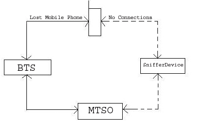
The sniffer is basically a transceiver that works in the frequency which is in the special unused range that is operated by the service provided or it can designed to operate at a frequency that is of much different frequency than the one that is being used by the nearby cells as there may be possibility of interference by the device with the devices in the nearby cells. The working for the device is as follows. The fig 2 &3 shows the working of the sniffer ; as given in the fig2 it gives the normal operation of the mobile with the base station and there is a BTS that acts as a middle man in the process of communication between the mobile and the MTSO which is popularly known as MSC or Mobile Switching Centre .There is always a two way communication between devices and before the establishment of the communication the authentication of the SIM card that has the IMSI or the International Mobile Subscriber Identifier .This IMSI number helps in the authorization of the user. The second authentication is the authentication of the handset, which is done in EIR or the Equipment Identifier Register. This register is located at the MSC and it contains the IMEI number of the lost handset and if the signal is obtained from the normal one then the two way communication is established.


The IMEI of the lost mobile phone number once has been reported to the service provider, who keeps in track of the record of lost mobile phones. The MTSO or the MSC which keeps in track of all the mobile phones with IMEI number and the IMSI number has the information of the lost mobile phones location which means the location of the cell where the lost device is because of the two way communication with the device the BTS of the lost device is known to MSC. From this information regarding the cell in which the device is located the sniffer device is introduced.Fig 3 . The connection of the sniffer device with the lost mobile phone.

Here the signal strength of the received signal is obtain antenna pattern is plotted once the signal of the mobile is obtained. The no. of antenna pattern for different position of same mobile phone is used to find the exact location. But however in this method the directional antenna used much be of a very small beam width this helps in more accurate process of detection. Fig4 the sniffer shown in fig tries to communicate with the lost mobile.
After getting connected with the mobile it creates a virtual cell pattern and thus helps in the detection of lost mobile phones.
5.CONCLUSION:
Since the boom of the mobile phone for the purpose of the communication there has been a large no. of complaints regarding the mobile phone that is being lost and there has been no effective method developed for detecting the lost device. The given paper dealt about the idea of development “Sniffer for the detection of lost Mobile phones” paves a way by means of which the lost mobile phones can be recovered. But the process of detection is yet to be developed through the software and demo has been developed and is with the authors. The demo has been written in VB that gives the over view of how the lost mobile is being detected and the software has been written in C. The SQL has to be used for the purpose of querying and the internal architecture is of lesser complexity compared to the base station as this mainly involves the control signal and there is no need for the voice process.

The design involved the following:
Design of the sniffer base station design of unidirectional l antenna, development of software for tracking. Though this method appears to be a little bit complex involving the design of the sniffer but however for large scale detection the overall effective cost of the design and the detection scales down.

There are certain boundary conditions or criteria that have to be qualified for the identification of the lost mobile like the power of the mobile should be good enough , the mobile phone should not be in the shadow region etc., but however this method can be improved by using modern technologies and devices.

APPENDIX

IMEI:
International Mobile Equipment Identifier.

SNIFFER:
The small transceiver used for detecting lost mobile phone.

IMSI:
International Mobile Subscriber Identifier.

BTS: Base transceiver station.

MTSO: Mobile Telephone Switching Office.

MSC: Mobile Station Switching Controller.

Ok friends,its all about sniffer device which i want to discuss.I hope it was quite understandable.Please leave comments in favour if you like and you can give suggestion also if I did any mistake.............
I will post new artical soon.....keep on watching.........bye

Seminar on virtual reality

Hello friends,
In this article i will discuss about virtual reality topic for presenting good seminar by computer science students.
Overview
Introduction
Types
Devices
VRML
Applications
Future

Introduction
Virtual Environment (VE)
 A computer generated world with which the user can interact
 Interaction can vary from looking around to interactively modifying the world.
Classroom is a VE


What is virtual reality (VR)?
 A computer generated, immersive (or wide field), multi-sensory information program which tracks a user in real time.
 Trying to mimic real world
 Immerse in 3-D visual world
Types
 Immersive
 Augmented
 Text-based
 Desktop (Window on a World)
 Video Mapping


What is Immersive VR?
In this type of VR in which the user becomes immersed (deeply involved) in a virtual world. It is also a form of VR that uses computer related components.
Types of Non-immersive VR
 Text-based VR: when a reader of a certain text form a mental model of this virtual world in their head from the description of people , places and things.
 Augmented VR: the idea of taking what is real and adding to it in some way so that user obtains more information from their environment.
Devices
Head Mounted Displays (HMD):
This was the first device providing its wearer with an immersive experience. Evans and Sutherland demonstrated a head-mounted stereo display already in 1965.

Motion Trackers
 Keep track of position
• Inertial boxes
• Sonic Discs
• Potentiometers
 Head trackers & body trackers


Binocular Omni-Orientation Monitor (BOOM)
BOOM is a head coupled stereoscopic display device. Screens and optical system are housed in a box that is attached to a multi-link arm.
pg.


Cave Automatic Virtual Environment (CAVE)
 A room with projections on all walls, floor and ceiling
 The users wear shutter glasses to get a 3D view of the world.
 The users are able to move and control the environment with some kind of input mechanism
• Camera
• Device in hand

Input Devices
 Data gloves
 Joysticks
 Hand-held wands
 Body sensors


Virtual reality Modeling Language (VRML)
Most exciting is the ongoing development of VRML on the World Wide Web. In addition to HTML (Hypertext Markup Language), that has become a standard authoring tool for the creation of home pages, VRML provides three-dimensional worlds with integrated hyperlinks on the Web. Home pages become home spaces.
Characteristics of VRML
• Not a programming language like c++ or java
• Descriptive (rather than procedural) like HTML
• File formats contains human readable and editable ASCII text
Applications
Architecture
Training
Medicine
Engineering and Design
E-Commerce
Entertainment
Manufacturing
Architecture
An area in which virtual reality has tremendous potential is in architectural design. Already being created are architectural "walk-through" that allow designers and clients to examine homes and office buildings, inside and out, before they're built. With virtual reality, designers can interactively test a building before construction begins.
Medicine
a)Researchers are using virtual reality technology to create 3-D ultrasound images to help doctors diagnose and treat congenital heart defects in children
b)The medical application of VR was stimulated initially by the need of medical staff to visualize complex medical data, particularly during surgery and for surgery planning, and for medical education and training.


Training
a)United States: The military used it as flight simulators to train pilots. b)National Aeronautics and Space Administration (NASA) use VR technology to construct a model of the Hubble Space Telescope (HST) .in September, 1993, approximately 100 members of the NASA HST flight team received over 200 hours of training using the VR...


Augmented Reality
HUD’s on cars


AR Museums
Information Visualization

Visualization

Future
1999 10% of the world's computing power was non-human
2029 99% of the world’s computing capacity will be non-human

In the past, computing power has doubled approximately every 18 months, a trend that is known as Moore’s Law. If this is the case then we should have a computer powerful enough to run immersive VR programs in our own homes by the year 2037.

Seminar on VSat

Hello friends,
This article presenting you the vsat technology.It is an interesting seminar topic for computer science students.
INDEX

S.NO. TOPIC
NO.
1 INDEX
2 INTRODUCTION
3 NEED FOR VSAT
4 WHAT VSAT DOES
5 COMPONENTS
6 OUTDOOR UNIT
7 INDOOR UNIT
8 SYSTEM ARCHITECTURE
9 OVERVIEW
10 ADVANTAGES
11 DISADVANTAGES


Introduction

Low cost business terminal with small antennas (generally less than 2 meters in diameter) are often termed Very Small Aperture Terminals (VSATs). VSATs are software driven earth station used for reliable transmission of data video or voice via satellite.

These are usually perceived as being two way data terminals, though strictly speaking many of the systems used for data broadcast are really one-way VSATs. Taking the USA as an example, approximately half of all installed VSATs are only used for one way data links.

ETSI take a different definition for a VSAT as a one or two-way terminal used in a star, mesh or point to point network. Antenna size is restricted to being less than or equal to 3.8 m at Ku band and 7.8 m at C band.

A more general definition is that a network is a VSAT network if it consists of a large high performance hub earth station (with an antenna of up to 9 m in diameter) and a large number of smaller, performance terminals. Being completely general, these small terminals can be receive only, transmit only or transmit/receive. Even this definition is not universal. Meshed VSAT networks exist in which all terminals have the same size and performance.


NEED FOR VSAT


Vsat n/w provides rapid, reliable satellite transmission of data, voice & video to an unlimited no. of geographical dispersed sites or from these sites to main stations, No matter how remote or dispersed your headquarters. VSAT can provide remote diagnostics, remote monitoring, and data streaming services from remote or hazardous sites.

WHAT EXACTLY THE VSAT DOES:

In a typical satellite Internet deployment, the remote site(s) communicate with the satellite hub and through the hub to other sites on the Internet, sometimes including a VPN between the satellite Internet hub and a corporate data center.
Sometimes two satellite remote sites will need to connect directly to each other. Subscribing each site to the VSAT Systems LLC broadband satellite service will allow direct communication while allowing each site to access the Internet in the usual manner.

This configuration will, however, produce double the amount of satellite latency when communicating directly between the sites due to the second satellite “hop.” See the diagram below.

COMPONENTS OF VSAT

1. Satellite
2. Parabolic shaped antenna
3. An outdoor unit (ODU)
4. An Indoor Unit (IDU)


Satellite: The ideal orbit for a communications satellite is geostationary, or motionless relative to the ground. Satellites used for communications are almost exclusively to the ground. Satellites used for communications are almost exclusively in the geostationary orbit, located at 36000Km above the equator. In line with ITU stipulations, for avoiding interference, all satellites are placed 2 degree apart. This places a maximum limit of 180 satellites operating in a geostationary orbit.

However, with a view to maximize the utilization of orbital slots, Co-located satellites are being deployed. Co-located satellites are separated by 0.1 degree in space or approximately 30 Kms. Signal interference from the Co-located satellites is prevented by using orthogonal polarizations. Hence a ground station equipment can receive signals from two Co-located satellites without any reorientation of the antenna. The signals can be differentiated based on their polarizations.


Space segment: Space Segment is available from organizations which have procured satellites, arranged launches and conducted preliminary tests in-orbit and who then operate these satellites on commercial basis.


Transponders: Contained in the satellite body are a number of transponders or repeaters. These transponders perform the following functions :

• Signal Reception – It receives the signal up linked by a VSAT and/or hub.
• Frequency Translation – The frequency, known as the received signal is translated to a different frequency translation ensures that there is no positive feedback and also avoid interference related issues.
• Amplification – The transponder also amplifies the downlink signal.


The number of transponders determines the capacity of a satellite. The INSAT series of transponders in various frequency bands. Each transponder typically has a bandwidth of 40 MHz. The various frequency bands are as below –


Frequency Band Uplink (GHz)
Earth Station to satellite Downlink (GHz)
Satellite to Earth Station
C Band 5.925 to 6.425 3.700 to 4.200
Extended C Band 6.725 to 7.025 4.500 to 4.800
Ku Band 14.000 to 14.500 10.950 to 11.700


Internationally Ku-Band is a popular frequency band in use. The Ku-Band by virtue of its higher frequency can support traffic with smaller antenna sizes in comparison to C/Ext-C Band. It is, however, susceptible to rain outages making it unsuitable for use in South East Asian regions. Indian service providers are presently allowed to hire space segment only on the INSAT series of satellites and is not a standard band available internationally.


Parabolic shaped antenna: Typically, interactive Ku-band antenna sizes range from 75 centimeters to 1.8 meters and C-band from 1.8 meters to 2.4 meters. One way systems can use antennas as small as 45 centimeters.


Outdoor Unit (ODU):

The outdoor unit consists of an Antenna and Radio Frequency Transceiver. (RFT). The antenna size is typically 1.8 meter or 2.4 meter in diameter, although smaller antennas are also in use. The antenna system comprises of a reflector, feed horn and a mount. The size of a VSAT antenna varies from 1.8 meters to 3.8 meters. The horn is mounted on the antenna frame at its focal point by support arms. The FEED HORN directs the transmitted power towards the antenna dish or collects the received power from it. It consists of an array of microwave passive components. Antenna size is used to describe the ability of the antenna to amplify the signal strength.

The RFT is mounted on the antenna frame and is interconnected to the feed horn. Also termed as outdoor electronics, RFT, in turn, consists of different subsystems.

These include low noise Amplifiers (LNA) and down converters for amplification and down conversion of the received signal respectively. LNAs are designed to minimize the noise added to the signal during this first stage of the converter as the noise performance of this stage determines the overall noise performance of the converter unit. The noise temperature is the parameter used to describe the performance of a LNA.

UP converters and High Powered Amplifiers (HPA) are also part of the RFT and are used for up converting and amplifying the signal before transmitting to the feed horn. The Up/Down converters convert frequencies between intermediate frequency (Usually IF level 70 MHz) and radio frequency. For Extended C band, the down converter receives the signal at 4.500 to 4.800 GHz and the up converter converts it to 6.725 to 7.025 Ghz. The HPA ratings for VSATs range between 1 to watts.


Indoor Unit (IDU):


The indoor unit functions as a modem and also interfaces with the end user equipment like stand alone PCs, LANs, Telephones or an EPABX. The IDU consists of modulators which superimpose the user traffic signal on a carrier signal. This is then sent to the RFT for up conversation, amplification and transmission. It also consist of demodulators which receive the signal from the RFT in the IF range and demodulates the same to segregate the user traffic signal from the carrier. The IDU also determines the access schemes under which the VSAT would operate. The IDU also interfaces with various end user equipment, ranging from stand alone computers, LAN’s, routers, multiplexes, telephone instruments, EPABX as per the requirement. It performs the necessary protocol conversion on the input data from the customer end equipment prior to modulation and transmission to the RFT. An IDU is specified by the access technique, protocols handled and number of interface ports supported.


The VSAT is configurable via software downloads without site visits. The VSAT software, which includes the TCP acceleration and the routing functionalities, (such as Static routing, RIP and IRDP) is embedded into the IDU. A satellite modem is different than a telephone modem, and is used to convert the data, video, or voice generated by the customer application for transmission over satellite. The modem takes the signals from your computer, phone or other device and changes them so they can be sent to the ODU which transmits them out to the satellite and eventually to other ground stations.


The IDU is responsible for the transfer of the data and video images between your network and the ODU. IDUs may even use a hard drive to provide content storage, caching of data and video. One side of the IDU connects to the coaxial cable from the ODU and the other attaches to network equipment. IDUs come with various port configurations to meet a variety of network applications requirements. For instance, IDUs come with Ethernet, USB, and/or audio and video ports for audio and video


SYSTEM ARCHILTECTURE:


Configurations Used

• Point to point configuration
• Broadcast configuration
• STAR configuration
• MESH configuration
• Hybrid configuration (Star & Mesh both)


Signal Types and Characteristics

The outbound data stream from the hub is transmitted at a relatively high data rate (typically 56 to 1024 Kb/s) using TDM. The bit stream consists of a synchronization word followed by a series of messages in time slots directed towards individual VSAT terminals. Broadcast messages to all remote VSAT terminals are also generally permitted.

Out bounds are transmitted continuously (i.e. duty cycle 100%) as a TDM stream. The number of out bounds per network is determined by the traffic statistics, packet length as well as the outbound data rate.

The out bounds for a network are generally grouped together at either the top or the bottom of the leased bandwidth.

The inbound carrier is often accessed using ALOHA or Slotted ALOHA. If a higher capacity is required, a separate channel can be dedicated to ALOHA or Slotted ALOHA access requests and a demand assigned TDMA access scheme established.

Inbound slotted ALOHA carriers information rates are usually between 2.4 and 16 Kb/s. Inbound TDMA or SCPC carriers used for file transfer usually have information data rates between aaa56 Kb/s and 256 Kb/s. All carriers are BPSK or QPSK modulated and have rate ½ or 2/3 Forward Error Correction (FEC). This ensures that bit error rates are low (typically 10 or 10 which is comparable to ISDN).

Remote terminals transmit in TDMA bursts in either a pre-assigned inbound channel slot or in any inbound channel slot depending on the manufacturer.


Several different inbound TDMA access systems are used depending on traffic characteristics and the manufacturer.

In a shared hub network, individual customers are often, but not always, allocated one or more dedicated out bounds and several inbounds.

If the traffic mix is a combination of short interactive messages and long file transfers it is often worthwhile to use a technique called Adaptive ALOHA/TDMA. VSATs which have large blocks of data to transmit request dedicated TDMA time slots and use TDMA. The other VSAT terminals in the network use slotted ALOHA and avoid the assigned time slots. Alternatively, dedicated SCPC carriers can be temporarily assigned for file transfer.
Each TDM outbound carries a continuously transmitted bit stream which is divided into frames.

The start of a frame is denoted by a framing packet contain a unique word (UW) and a control word (CNTRL) which, together, provide framing, timing and control information.

The rest of the frame is filled by (generally) fixed length data packets which each contain:

• F preamble
• HDR header – giving IDU address and control information
• FCS frame check sequence
• F postamble

Outbound data packets typically contain between 50 and 250 bytes in transactional networks.

Each TDMA inbound contains frames which are synchronized to the outbound frames. Each inbound frame is divided into slots. Individual IDUs transmit in these slits in a manner depending on the access modes available to the particular system and how the network has been set up.


Each inbound packet consists of:


• F preamble
• HDR header – giving IDU address and control information
• FCS frame check sequence
• F postamble

Inbound data packets typically contain between 50 and 250 bytes in transactional networks.

The main inbound transmission modes used are:

Aloha, in which an IDU can transmit data packets at any time in a particular inbound frequency slot. Transmissions in any particular frequency slot are intermittent with a peak traffic duty cycle of 10 to 15%.

Slotted Aloha, in which an IDU can transmit data packets in any slot (or any of a predetermined number of slots) in a particular inbound frequency slot. Transmissions in any particular frequency slot are intermittent with a peak traffic duey cycle of 25 to 30%.


Fixed Assignment, in which specific time slots in an inbound frequency slot are permanently, or for the duration of a particular transmission, assigned to a particular IDU. This is often used for batch transmission and for telephony. Transmissions in any particular frequency slot are intermittent but can have a peak traffic duty cycle of 100% if that particular inbound is carrying telephony traffic or several batch file transfers from different IDUs.

Dynamic Assignment, in which time slots in an inbound frequency slot are dynamically, assigned to a particular IDU in line with ongoing traffic demands. Transmissions in any particular frequency slot are intermittent with a peak traffic duty cycle of from 25 to 30% to approaching 100%, depending on the traffic nix.

Most interactive hubbed VSATs now have protocol stacks which map, at least notionally, onto the OSI stack.

Network layer spoofing is provided by many VSATs to minimize the impact of the data layer protocol and, particularly, the satellite transmission delay, on the throughput of the satellite link.


TDM/TDMA Connection Set Up

When the network is established, or when additional remote terminals are added to the network, remote remote terminal addresses and characteristics (i.e. card fits and port addresses) are entered into a network database which is used as a routing table by the operational system. This database establishes permanent virtual circuits between ports at the user interface of the hub and the ports at the user interfaces of the remote terminals. In those products which permit the dedication of the assignment of capacity on request, or dynamic variable assignment, the database also establishes permanent virtual circuits between the IDU controllers at the remote terminals and the NCC.

This arrangement allows the normal transactional traffic carried by the network to be switched without an individual call set up procedure.

A packet sent by a particular IDU carries addressing information identifying both the source and destination. This allows the hub switch to route the packet to the correct user interface port without additional signaling traffic.

This same procedure is used for intra network signaling to set up assignments for the temporary or permanent assignment of channels to a particular IDU port/hub port pair (for example, telephony or batch data transfers). Call set up information is sent as a transactional data packet as described above, except that the destination address at the hub is the NCC.

Hub Station
The hub station is usually a relatively large, high performance earth station with an antenna diameter of anything between 6 and 9m. The hub consists of a control centre which manages the network as well as microwave equipment, including an outdoor antenna, for the transmission and reception of signals. A substantial amount of interfacing equipment necessary to support the wide range of terrestrial interfaces required at the hub completes the installation. This equipment is usually mounted in several racks.


Hub stations can be shared between several networks, resulting in a sharing of costs. Two principal options for network implementation can be adopted. Firstly, some very large users will wish to purchase their own dedicated VSAT networks including a hub. Other users will choose to buy or lease the user terminals and to lease access to hub which will be owned by the system operator.

The hub station consists of several main subsystems; except for the antenna these are usually fully redundant with automatic switchover in the event of failure:

• A switch (generally a packet switch) which controls routing between host ports and the modulator and demodulator ports, as well as adding and reading header address information which controls routing to and from individual IDUs
• One or more modulators which modulate the outbound carriers with the TDM stream generated by the switch (each outbound carrier has a dedicated modulator
• Abank of demodulators which receive the inbound carriers and extract the data packets and feed them to the switch.
• An RFT (radio frequency terminal), which contains:
• The transmit subsystem containing up converters which change the 70 or 140 MHz IF to the required transmit frequency before feeding it to the High Power Amplifier (HPA). If the hub only uses a single carrier for data it is possible to use a solid state power amplifier (SSPA), otherwise a more powerful Traveling Wave Tube Amplifier (TWTA) must generally be used. Uplink power control is often provided so that the power transmitted by the hub can be increased to compensate for high link attenuation due to precipitation in bad weather.
• The receive subsystem consisting of a Low Noise Amplifier (LNA) with a noise temperature usually between 150 and 175 K (Ku band) and a down converter to change the received frequency to the IF frequency (70 or 140 MHz).
• The antenna subsystem consisting of a large antenna (6 to 9 m in diameter) on a mount with a tracking system which allows the antenna to follow the satellite as it moves very slightly in the sky. A feed horn at the focus of the dish to collect the received signals from the antenna and to feed the transmit signals to it.
• An NCC (network control centre) which controls and monitors the operation of the hub and the IDUs in the network
• The primary power subsystem which guarantees the quality and continuity of the power supply for the hub. It typically contains power switching, an uninterruptible power supply with a large battery band and a diesel generator


Remote Terminals

In contrast to the hub station, the remote terminals are much simpler. To minimize total system costs, VSAT networks are designed to have a single expensive hub and a large number of much smaller remote terminals.

• A dish antenna, generally 0.55 to 2.4 m in diameter (though larger dishes are sometimes required), which can be wall, roof or ground mounted.
• The antennas are usually offset-fed parabolic ishes, although larger dishes tend to be centre-fed. Recently, to gain higher performance (in particular side lobe performance) dual reflector, Gregorian designs have started to become common. Several different materials are used for the dishes with spun aluminum, steel, fiberglass and reinforced plastic being the most popular
• An outdoor unit, which contains the microwave electronics for the terminal. This is usually the size of a shoe box, but it may be much smaller. If the ODU is large it is normally supported on the antenna mount behind the dish. Smaller ODUs can be attached directly to the rear of the feed assembly in front of the dish.
• The outdoor unit is usually all solid state with GaAs FETs used in the Low Noise Receiver and the High Power Amplifier. LNA noise temperatures are typically in the range 290 -225 K (Ku band) and HPA output powers are usually in the range 0.1 – 6 W (Ku band).
• An indoor unit, which provides the modulation, demodulation, multiplexing, demultiplexing and synchronization with the rest of the network and supports the user interfaces. This box is usually about the size of a domestic video recorder


Remote terminals usually support a wide range of common electrical interfaces such as RS-232, RS-422, V.35, as well as voice and TV. Several common protocols are also generally supported including SDLC, 3270 bisyne, X.25, asynch and Ethernet. Asynchronous data rates are typically available up to 9.6 kb/s. Synchronous data rates between 1.2 and 32 or 64 kb/s are also generally available.

Remote terminals have now become very reliable, with MTBFs of typically 25000 hours. Link availability is also usually designed to be high, with an end to end availability of better than 99.7% being quite common.


Advantages of VSATs

VSATs are an ideal option for networking because they enable Enterprise Wide Networking with high reliability and a wide reach which extends even to remote sites.

Last Mile Problem

Let us begin with the situstion where you have reliable high-speed links between city exchanges for meeting your communication requirements. But before you begin to feel comfortable, connections from the nearest exchange to your company’s office often fail. Consequently, stretching what is technically called the last mile problem into much longer distances. VSATs located at your premises guarantee seamless communication even across the last mile.

Reach


You must be well aware of the limitations faced by terrestrial lines in reaching remote and other difficult locations. VSATs, on the other hand, offer you unrestricted and unlimited reach.

Reliability

Uptime of upto 99.5 % is achievable on a VSAT network. This is significantly higher than the typical leased line uptime of approximately 80 to 85%.


Time

VSAT deployment takes no more than 4-6 weeks as compared to 4 to 6 months for leased lines.

Network

Management Maintenance


Flexibility


Disadvantages of VSATs

Speed


SECURITY

ALLIGNMENT

WHETHER PROBLEM (STOP WORKING IN ECLIPSE)

LIMITED SPECTRUM & THUS LIMITED BW


UNAVAILABILITY OF SKILLED PERSONS


CONCLUSION

VSAT N/W provides rapid, reliable satellite transmission of data, voice & video to an unlimited no. of geographical dispersed sites or from these sites to main station, No matter how remote or dispersed your operations are, VSATs provide a link to your headquarters. VSAT N/Ws are to every type of architecture like point to point configuration, star, mesh etc.

3D-Passward

Hello friends.
In this article i will discuss 3D passward seminar topic.

INTRODUCTION

Normally the authentication scheme the user undergoes is particularly very lenient or very strict. Throughout the years authentication has been a very interesting approach. With all the means of technology developing, it can be very easy for 'others' to fabricate or to steal identity or to hack someone’s password. Therefore many algorithms have come up each with an interesting approach toward calculation of a secret key. The algorithms are such based to pick a random number in the range of 10^6 and therefore the possibilities of the sane number coming is rare.

Users nowadays are provided with major password stereotypes such as textual passwords, biometric scanning, tokens or cards (such as an ATM) etc .Mostly textual passwords follow an encryption algorithm as mentioned above. Biometric scanning is your "natural" signature and Cards or Tokens prove your validity. But some people hate the fact to carry around their cards, some refuse to undergo strong IR exposure to their retinas(Biometric scanning).Mostly textual passwords, nowadays, are kept very simple say a word from the dictionary or their pet names, girlfriends etc. Years back Klein performed such tests and he could crack 10-15 passwords per day. Now with the technology change, fast processors and many tools on the Internet this has become a Child's Play.
Therefore we present our idea, the 3D passwords which are more customizable and very interesting way of authentication. Now the passwords are based on the fact of Human memory. Generally simple passwords are set so as to quickly recall them. The human memory, in our scheme has to undergo the facts of Recognition, Recalling, Biometrics or Token based authentication. Once implemented and you log in to a secure site, the 3D password GUI opens up. This is an additional textual password which the user can simply put. Once he goes through the first authentication, a 3D virtual room will open on the screen. In our case, let’s say a virtual garage. Now in a day to day garage one will find all sorts of tools, equipments, etc.each of them having unique properties. The user will then interact with these properties accordingly. Each object in the 3D space, can be moved around in an (x,y,z) plane. That’s the moving attribute of each object. This property is common to all the objects in the space. Suppose a user logs in and enters the garage. He sees and picks a screw-driver (initial position in xyz coordinates (5, 5, 5)) and moves it 5 places to his right (in XY plane i.e. (10, 5, 5).That can be identified as an authentication. Only the true user understands and recognizes the object which he has to choose among many. This is the Recall and Recognition part of human memory coming into play. Interestingly, a password can be set as approaching a radio and setting its frequency to number only the user knows. Security can be enhanced by the fact of including Cards and Biometric scanner as input. There can be levels of authentication a user can undergo.

EXISTING SYSTEM
Current authentication systems suffer from many weaknesses. Textual passwords are commonly used. Users tend to choose meaningful words from dictionaries, which make textual passwords easy to break and vulnerable to dictionary or brute force attacks. Many available graphical passwords have a password space that is less than or equal to the textual password space. Smart cards or tokens can be stolen. Many biometric authentications have been proposed. However, users tend to resist using biometrics because of their intrusiveness and the effect on their privacy. Moreover, biometrics cannot be revoked. The 3Dpassword is a multi factor authentication scheme. The design of the 3D virtual environment and the type of objects selected determine the 3D password key space. User have freedom to select whether the 3D password will be solely recall, recognition, or token based, or combination of two schemes or more.


PROPOSED SYSTEM

The proposed system is a multi factor authentication scheme that combines the benefits of various authentication schemes. Users have the freedom to select whether the 3D password will be solely recall, biometrics, recognition, or token based, or a combination of two schemes or more. This freedom of selection is necessary because users are different and they have different requirements. Therefore, to ensure high user acceptability, the user’s freedom of selection is important.
The following requirements are satisfied in the proposed scheme

1. The new scheme provide secrets that are easy to remember and very difficult for intruders to guess.
2. The new scheme provides secrets that are not easy to write down on paper. Moreover, the scheme secrets should be difficult to share with others.
3. The new scheme provides secrets that can be easily revoked or changed.


BRIEF DESCRIPTION OF SYSTEM
The proposed system is a multi factor authentication scheme. It can combine all existing authentication schemes into a single 3D virtual environment .This 3D virtual environment contains several objects or items with which the user can interact. The user is presented with this 3D virtual environment where the user navigates and interacts with various objects. The sequence of actions and interactions toward the objects inside the 3D environment constructs the user’s 3D password. The 3D password can combine most existing authentication schemes such as textual passwords, graphical passwords, and various types of biometrics into a 3D virtual environment. The choice of what authentication schemes will be part of the user's 3D password reflects the user's preferences and requirements. A user who prefers to remember and recall a password might choose textual and graphical password as part of their 3D password. On the other hand users who have more difficulty with memory or recall might prefer to choose smart cards or biometrics as part of their 3D password. Moreover user who prefers to keep any kind of biometric data private might not interact with object that requires biometric information. Therefore it is the user's choice and decision to construct the desired and preferred 3D password.

SYSTEM IMPLIMENTATION

The 3D password is a multi factor authentication scheme. The 3D password presents a 3D virtual environment containing various virtual objects. The user navigates through this environment and interacts with the objects. The 3D password is simply the combination and the sequence of user interactions that occur in the 3D virtual environment. The 3D password can combine recognition, recall, token, and biometrics based systems into one authentication scheme. This can be done by designing a 3D virtual environment that contains objects that request information to be recalled, information to be recognized, tokens to be presented, and biometric data to be verified.
For example, the user can enter the virtual environment and type something on a computer that exists in (x1 , y1 , z1 ) position, then enter a room that has a fingerprint recognition device that exists in a position (x2 , y2 , z2 ) and provide his/her fingerprint. Then, the user can go to the virtual garage, open the car door, and turn on the radio to a specific channel. The combination and the sequence of the previous actions toward the specific objects construct the user’s 3D password.
Virtual objects can be any object that we encounter in real life. Any obvious actions and interactions toward the real life objects can be done in the virtual 3D environment toward the virtual objects. Moreover, any user input (such as speaking in a specific location) in the virtual 3D environment can be considered as a part of the 3D password.
We can have the following objects:
1) A computer with which the user can type;
2) A fingerprint reader that requires the user’s fingerprint;
3) A biometric recognition device;
4) A paper or a white board that a user can write, sign, or draw on;
5) An automated teller machine (ATM) that requests a token;
6) A light that can be switched on/off;
7) A television or radio where channels can be selected;
8) A staple that can be punched;
9) A car that can be driven;
10) A book that can be moved from one place to another;
11) Any graphical password scheme;
12) Any real life object;
13) Any upcoming authentication scheme.

The action toward an object (assume a fingerprint recognition device) that exists in location (x1, y1 , z1 ) is different from the actions toward a similar object (another fingerprint recognition device) that exists in location (x2 , y2 , z2 ), where x1 = x2 , y1 = y2 , and z1 = z2 . Therefore, to perform the legitimate 3D password, the user must follow the same scenario performed by the legitimate user. This means interacting with the same objects that reside at the exact locations and perform the exact actions in the proper sequence.

3D PASSWORD SELECTION AND INPUT

Let us consider a 3D virtual environment space of size G ×G × G. The 3D environment space is represented by the coordinates (x, y, z) ∈ [1, . . . , G] ×[1, . . . , G] ×[1, . . . , G]. The objects are distributed in the 3D virtual environment with unique (x, y, z) coordinates. We assume that the user can navigate into the 3D virtual environment and interact with the objects using any input device such as a mouse, key board, fingerprint scanner, iris scanner, stylus, card reader, and microphone. We consider the sequence of those actions and interactions using the previous input devices as the user’s 3D password.
For example, consider a user who navigates through the 3D virtual environment that consists of an office and a meeting room. Let us assume that the user is in the virtual office and the user turns around to the door located in (10, 24, 91) and opens it. Then, the user closes the door. The user then finds a computer to the left, which exists in the position (4, 34, 18), and the user types “FALCON.” Then, the user walks to the meeting room and picks up a pen located at (10, 24, 80) and draws only one dot in a paper located in (1, 18, 30), which is the dot (x, y) coordinate relative to the paper space is (330, 130). The user then presses the login button. The initial representation of user actions in the 3Dvirtual environment can be recorded as follows:
(10, 24, 91) Action = Open the office door;
(10, 24, 91) Action = Close the office door;
(4, 34, 18) Action = Typing, “F”;
(4, 34, 18) Action = Typing, “A”;
(4, 34, 18) Action = Typing, “L”;
(4, 34, 18) Action = Typing, “C”;
(4, 34, 18) Action = Typing, “O”;
(4, 34, 18) Action = Typing, “N”;
3D VIRTUAL ENVIRONMENT DESIGN GUIDELINES

The design of the 3 D virtual environments affects the usability, effectiveness, acceptability of 3D password. The first step in building a 3D password system is to design a 3D environment that reflects the administration needs and the security requirements. The design of 3D virtual environments should follow these guidelines.

1) Real Life Similarity The prospective 3D virtual environment should reflect what people are used to seeing in real life. Objects used in virtual environments should be relatively similar in size to real objects (sized to scale). Possible actions and interactions toward virtual objects should reflect real life situations. Object responses should be realistic. The target should have a 3D virtual environment that users can interact
2) Object uniqueness and distinction every virtual object or item in the 3D virtual environment is different from any other virtual object. The uniqueness comes from the fact that every virtual object has its own attributes such as position. Thus, the prospective interaction with object 1 is not equal to the interaction with object 2. How ever, having similar objects such as 20 computers in one place might confuse the user. Therefore, the design of the 3D virtual environment should consider that every object should be distinguishable from other objects. Similarly, in designing a 3D virtual environment, it should be easy for users to navigate through and to distinguish between objects. The distinguishing factor increases the user’s recognition of objects. Therefore, it improves the system usability.
3) Three Dimensional Virtual Environment Size A 3D virtual environment can depict a city or even the world. On the other hand, it can depict a space as focused as a single room or office. A large 3D virtual environment will increase the time required by the user to perform a 3D password. Moreover, a large 3D virtual environment can contain a large number of virtual objects. Therefore, the probable 3D password space broadens. However, a small 3D virtual environment usually contains only a few objects, and thus, performing a 3D password will take less time.
4) Number of objects and their types Part of designing a 3D virtual environment is determining the types of objects and how many objects should be placed in the environment. The types of objects reflect what kind of responses the object will have. For simplicity, we can consider requesting a textual password or a fingerprint as an object response type. Selecting the right object response types and the number of objects affects the probable password space of a 3D password.
5) System Importance The 3D virtual environment should consider what systems will be protected by a 3D password The number of objects and the types of objects that Have been used in the 3D virtual environment should reflect the importance of the protected system.

3D PASSWORD APPLICATION

The 3D password can have a password space that is very large compared to other authentication schemes, so the 3D password’s main application domains are protecting critical systems and resources.

1. Critical server many large organizations have critical servers that are usually protected by a textual password. A 3D password authentication proposes a sound replacement for a textual password.
2. Nuclear and military facilities such facilities should be protected by the most
Powerful authentication systems. The 3D password has a very large probable password space, and since it can contain token, biometrics, recognition and knowledge based
Authentications in a single authentication system, it is a sound choice for high level security locations.
3. Airplanes and jet fighters Because of the possible threat of misusing airplanes
and jet fighters for religion, political agendas, usage of such airplanes should be protected by a powerful authentication system.

In addition, 3D passwords can be used in less critical systems because the
3D virtual environment can be designed to fit to any system needs. A small virtual environment can be used in the following systems like
1) ATM
2) Personal Digital Assistance
3) Desktop Computers & laptop logins
4) Web Authentication
5) Security Analysis

To analyze and study how secure a system is, we have to consider,
• How hard it is for the attacker to break such a system
▪ A possible measurement is based on the information content of a password space. It is important to have a scheme that has a very large possible password space which increases the work required by the attacker to break the authentication system.
▪ Find a scheme that has no previous or existing knowledge of the most probable user password selection.\

SECURITY ANALYSIS

3D Password space size
To determine the password space, we have to count all possible 3D passwords that have a certain number of actions, interactions, and inputs towards all objects that exist in the 3D virtual environments.

3D password distribution knowledge

Users tend to use meaningful words for textual passwords. Therefore finding these different words from dictionary is a relatively simple task which yields a high success rate for breaking textual passwords. Pass faces users tend to choose faces that reflect their own taste on
facial attractiveness, race, and gender.
Every user has different requirements and preferences when selecting the appropriate 3D
Password. This fact will increase the effort required to find a pattern of user’s highly selected 3D password. In addition, since the 3D password combines several authentication schemes into a single authentication environment, the attacker has to study every single authentication scheme and has to discover what the most probable selected secrets are. Since every 3D password system can be designed according to the protected system requirements, the attacker has to separately study every 3D password system. Therefore, more effort is required to build the knowledge of most probable 3D passwords.

Attacks and Countermeasures
To realize and understand how far an authentication scheme is secure, we have to consider all possible attack methods. We have to study whether the authentication scheme proposed is immune against such attacks or not. Moreover, if the proposed authentication scheme is not immune, we then have to find the countermeasures that prevent such attacks. In this section, we try to cover most possible attacks and whether the attack is valid or not. Moreover, we try to propose countermeasures for such attacks.

1)Brute Force Attack: The attacker has to try all possible 3D passwords. This kind of attack is very difficult for the following reasons.
a. Time required to login The total time needed for a legitimate user to login may vary depending on the number of interactions and actions, the size of the 3D virtual environment, and the type of actions and interactions. Therefore, a brute force attack on a 3D password is very difficult and time consuming
b. Cost of attacks the 3D virtual environment contains biometric recognition objects and token based objects. The attacker has to forge all possible biometric information and forge all the required tokens. The cost of forging such information is very high, therefore cracking the 3D password is more challenging. The high number of possible 3D password spaces leaves the attacker with almost no chance of breaking the 3D password.
2)Well-Studied Attack : The attacker tries to find the highest probable distribution of 3D passwords. In order to launch such an attack, the attacker has to acquire knowledge of the most probable 3D password distributions. This is very difficult because the attacker has to study all the existing authentication schemes that are used in the 3D environment. It requires a study of the user’s selection of objects for the 3D password. Moreover, a well studied attack is very hard to accomplish since the attacker has to perform a customized attack for every different 3D virtual environment design. This environment has a number of objects and types of object responses that differ from any other 3D virtual environment. Therefore, a carefully customized study is required to initialize an effective attack.
3)Shoulder Surfing Attack :An attacker uses a camera to record the user’s 3D password or tries to watch the legitimate user while the 3D password is being performed. This attack is the most successful type of attack against 3D passwords and some other graphical passwords. However, the user’s 3D password may contain biometric data or textual passwords that cannot be seen from behind. Therefore, we assume that the 3D password should be performed in a secure place where a shoulder surfing attack cannot be performed.
4)Timing Attack: In this attack, the attacker observes how long it takes the legitimate user to perform a correct sign in using the 3D password. This observation gives the attacker an indication of the legitimate user’s 3D password length. However, this kind of attack alone cannot be very successful since it gives the attacker mere hints. Therefore, it would probably be launched as part of a well studied or brute force attack. Timing attacks can be very effective if the 3D virtual environment is poorly designed.

CONCLUSION
The 3D password is a multi factor authentication scheme that combines the various authentication schemes into a single 3D virtual environment. The virtual environment can contain any existing authentication scheme or even any upcoming authentication scheme or even any upcoming authentication schemes by adding it as a response to actions performed on an object. Therefore the resulting password space becomes very large compared to any existing authentication schemes. The design of the 3D virtual environment the selection of objects inside the environment and the object's type reflect the resulted password space. It is the task of the system administrator to design the environment and to select the appropriate object that reflects the protected system requirements. Designing a simple and easy to use 3D virtual environment is a factor that leads to a higher user acceptability of a 3D password system. The choice of what authentication scheme will be part of user's 3D password reflects the user's preferences and requirements.

Sky-x Technology

Hello friends,
This article is about a seminar topic named sky-x Technology.


SKY X TECHNOLOGY
=======================

Satellites are attractive option for carrying internet and other IP traffic to many locations across the globe where terrestrial options are limited or [censored] prohibitive. But data networking on satellite is faced with overcoming the large latency and high bit error rate typical of satellite communications as well as the asymmetric bandwidth design of most satellite network.Satellites are ideal for providing internet and private network access over long distance and to remote locations. However the internet protocols are not optimized for satellite conditions. So the throughput over the satellite networks is restricted to only a fraction of available bandwidth.Mentat , the leading supplies of TCP/IP to the computer industry have overcome their limitations with the development of the Sky X product family.The Sky X system replaces TCP over satellite link with a protocol optimized for the long latency, high loss and asymmetric bandwidth conditions of the typical satellite communication. The Sky X family consists of Sky X Gateway, Sky X Client/Server and Sky X OEM products.Sky X products increase the performance of IP over satellite by transparency replacing. The Sky X Gateway works by intercepting the TCP connection from client and converting the data to Sky X protocol for transmission over the satellite. The Sky X Client /Server product operates in a similar manner except that the Sky X client software is installed on each end users PC.Connection from applications running on the PC is intercepted and send over the satellite using the Sky X protocol.
================================================================================
INTRODUCTION

Satellites are ideal for providing internet and private network access over long distance and to remote locations. However the internet protocols are not optimized for satellite conditions and consequently the throughput over the satellite networks is restricted to only a fraction of available bandwidth. We can over come these restrictions by using the Sky X protocol.
The Sky X Gateway and Sky X Client/Servers systems replaces TCP over satellite link with a protocol optimized for the long latency, high loss and asymmetric bandwidth conditions of the typical satellite communication. Adding the Sky X system to a satellite network allows users to take full advantage of the available bandwidth. The Sky X Gateway transparently enhances the performance of all users on a satellite network without any modifications to the end clients and servers. The Sky X Client and the Sky X Server enhance the performance of data transmissions over satellites directly to end user PC’s, thereby increasing Web performance by 3 times or more and file transfer speeds by 10 to 100 times. The Sky X solution is entirely transparent to end users, works with all TCP applications and does not require any modifications to end client and servers

Sky X products are the leading implementation of a class of products known variously as protocol gateway TCP Performance Enhancing Proxy (TCP/PEP) , or satellite spoofer.The Sky X gateways are available as ready to install hardware solutions which can be added to any satellite network.
The Sky X family consists of the Sky X Gateway, Sky x Client/Server and the sky X OEM products. The Sky X Gateway is a hardware solution designed for easy installation into any satellite network and provides performance enhancement for all devices on the network. The Sky X Client/Server provides performance enhancement to individual PC’s.

PERFORMANCE OF TCP OVER SATELLITE
Satellites are an attractive option for carrying Internet and other IP traffic to many locations across the globe where terrestrial options are limited or price prohibitive. However data networking over satellites is faced with overcoming the latency and high bit error rates typical of satellite communications, as well as the asymmetric bandwidth of most satellite networks
Communication over geosynchronous satellites, orbiting at an altitude of 22,300 miles has round trip times of approximately 540 m/s, an order of magnitude larger than terrestrial networks. The journey through the atmosphere can also introduce bit errors into the data stream. These factors, combined with backchannel bandwidth typically much smaller than that available on the forward channel, reduce the effectiveness of TCP which is optimized for short hops over low-loss cables or fiber.Eventhough the TCP is very effective in the local network connected by using cables or optical fibers by using its many features such as LPV6, LPsec and other leading-edge functionality. Also it will work with real time operating systems.TCP is designed for efficiency and high performance ,and optimized for maximum throughput and the highest transaction speeds in local networks.
But the satellite conditions adversely interact with a number of elements of the TCP architecture, including it s window sizing, congestion avoidance algorithms, and data acknowledgment mechanisms, which contribute to severely constrict the data throughput that can be achieved over satellite links. Thus the advantages achieved by TCP in LAN’s are no longer effective in the satellite link. So it is desirable to design a separate protocol for communication through the satellite to eliminate the disadvantages of using TCP over the satellite link. The adverse effects of using TCP over satellite link in its various features are as follows:
Window size
TCP utilizes a sliding window mechanism to limit the amount of data in flight. When the window becomes full, the sender stops transmitting until it receives new acknowledgement. Over satellite networks, where acknowledgements are slow to return, the TCP window size gradually sets a hard limit on the maximum throughput rate. The minimum window size needed to fully utilize an error-free link known as the “bandwidth-delay product” is 100 KB for a T1 satellite link and 675 KB for a 10 Mbps link. However many implementations of TCP are limited to maximum window size of 64 KB and most operating systems use a default window size of only 8 KB , imposing a maximum throughput rate over a satellite link of only 128 Kbps per connection , regardless of the bandwidth available. So the high bandwidth available in the network is no longer effective, thus the data availability in a client is restricted to a small fraction of the available bandwidth. Thus the window sizing mechanism of the TCP limits the rate of flow of data through satellite link.
The simple, heuristic data acknowledgment scheme used by TCP does not adapt well to long latency or highly asymmetric bandwidth conditions. To provide reliable data transmission, the TCP receiver constantly sends acknowledgments back to the sender. The sender does not assume that any data is lost or corrupted until a multiple of the round-trip time has passed without receiving an acknowledgment. This algorithm does not respond well over satellite networks where the round-trip time is long and error rates can be high. Further, this constant stream of acknowledgments wastes precious back channel bandwidth and if the back channel is small, the return of the acknowledgments to the sender can become the system bottleneck. The acknowledgements and error messages will always dominate the data transfer and the rate of flow reduces very much.
Congestion Avoidance
In order to avoid the possibility of congestive network meltdown, TCP usually assumes that all data loss is caused by congestion and responds to this by reducing the transmission rate. However, over satellite links, TCP misinterprets the long round-trip time and bit errors as congestion and responds inappropriately. Similarly, the TCP “Slow Start” algorithm, which over the terrestrial infrastructure prevents new connections from flooding an already congested network, forces an excessively long ramp-up period for each new connection over satellite. While these congestion avoidance mechanisms are vital in routed environments, they are ill-suited to single-path satellite links.
So the congestion avoidance mechanisms used by TCP is also not suited for the satellite link since it reduces the data flow through the network and thus reduces the overall rate of data transfer.
SKY X SYSTEM
Sky X Technology Overcomes TCP Performance Limitations
Sky X products increase the performance of IP over satellite through a combination of protocol connection-splitting, data compression, and Web pre-fetching, while remaining entirely transparent to end users. The Sky X gateway works by transparently replacing TCP connections from the client and converting the data to Xpress Transport protocol (XTP) for the hop over the satellite link which is the protocol optimized for satellite conditions.

SKY X GATEWAY OPERATION
The Sky X gateway works by intercepting the TCP connection from the client and converting the data to the Xpress Transport Protocol (XTP) for transmission over the satellite. The Sky X gateway on the opposite side of the satellite link translates the data back to TCP for communication with the server. This architecture offers vastly improved performance while remaining entirely transparent to the end user and fully compactable with the internet infrastructure. No changes are required to the client or server and all applications continue to function without modification. This architecture is also referred to as TCP Performance Enhancing Proxy (TCP-PEP) and is compactable with IETF RFC 3135.

The Sky X gateway splits the single TCP connection into three separate components. A TCP connection on the remote side between the client and Sky X gateway, an XTP connection involving Sky X protocol over the satellite between the two Sky X gateways and a TCP connection between the opposite Sky X gateway and server.
XTP is a reliable, transport-layer protocol specifically designed to operate efficiently over high-speed networks and offers a level of performance not possible with TCP on long latency, high loss satellite links. XTP is an open standard developed by the XTP Forum, a non-profit organization composed of networking protocol researchers, implementers, and user organizations.
By splitting the end-to-end TCP connection, the segment over the satellite can take advantage of the performance of XTP. TCP congestion avoidance mechanisms remain in place over the terrestrial connections to protect the stability of the routed network. The two Sky X gateways pass control data between each other, allowing the Sky X gateway on the opposite side of the satellite to appear to be the original source or destination device. This architecture maintains full TCP reliability and end-to-end flow control.

Web Pre-Fetch functionality further enhances the performance of HTTP transfers over the satellite link by pro-actively retrieving the many embedded objects on a Web page along with the requested HTML page. The Sky X system delivers the Web objects to the Sky X gateway on the client side of the satellite link where they can be served locally when requested by the browser, avoiding the satellite delay.
The Sky X gateway XR10, XH45, and XH155 are available as ready-to-install hardware solutions which can be added to any satellite network. The Sky X Client software installs directly on the PCs of end-users and works in conjunction with a Sky X Server SS10 or SS45 hardware unit located at the network hub. Mentat also licenses the Sky X gateway technology in software source code form for integration with satellite modems, VSATs, routers, caching systems, or any other satellite connectivity equipment. The Sky X gateway can also be used in multilink configurations where a single Sky X gateway hub unit enhances the performance of multiple separate outbound links from a single uplink facility.
Mentat SkyX Gateway 250 - gateway (discontinued)

1. Manufacturer's description
Manufacturer description
The SkyX 250 is ideal as a remote, or hub, device to bring high network performance to lower bandwidth networks. Also use at both sides of the link in a point-to-link as well as in fully meshed networks

The Sky X Client / Server product operates similarly to the Sky X gateway except the Sky X Client software is installed directly onto the client PC. Connections from applications running on the PC are intercepted and sent over the satellite using Sky X protocol. At the network hub, a Sky X Server establishes a TCP connection with the destination server.
Sky X Client/Server
The Sky X Client / Server increases the throughput and efficiency of network access over satellites by transparently replacing TCP with the Xpress Transport Protocol (XTP) for the satellite segment of the connection. Combined with data compression and Web-specific enhancements, the Sky X system provides maximum performance under the long latency, high loss, and asymmetric bandwidth conditions typical of satellite communications.
The sky X client/server system enhances the performance of the internet and private network access over satellite links. The sky X client software installed on the PC’s of the end user, works in conjunction with a sky X server hardware unit located at the network hub. Through the use of a unique connection splitting and protocol –translation system, the sky X client/server system overcomes the deficiencies of TCP/IP in satellite –based networks while remaining entirely transparent to end-user applications. The sky X client is ideal for use with any satellite receiver card or set –top box
Sky X Client / Sky X Server Operation
The Sky X Client / Server increases the throughput and efficiency of network access over satellites by transparently replacing TCP with the Xpress Transport Protocol (XTP) for the satellite segment of the connection. Combined with data compression and Web-specific enhancements, the Sky X system provides maximum performance under the long latency, high loss, and asymmetric bandwidth conditions typical of satellite communications.

The Sky X Client, installed on Microsoft Windows-based computers, transparently intercepts TCP connections from applications running on the PC and transmits the data over the satellite link using XTP. The Sky X Server, installed at the hub of the satellite network, establishes a new TCP connection for communication with any device on the local network or over the Internet. Through this unique, patented architecture, the Sky X Client / Server system requires no proxy settings while providing performance enhancement for all TCP applications.
The Sky X Server is available in two models namely the SS10 and SS45. The SS10 provides Sky X enhancement for links of up to 10 Mbps while the SS45 provides Sky X enhancement for links of up to 45 Mbps

Sky X Multicast Fan-Out
Computer networking traditionally relies on unicast data transfers which establish point-to-point connections between devices. In situations where the same data is transferred to multiple users, the server must send a copy of the file to each recipient independently. This process is both time consuming and wastes much of the bandwidth resources.
In contrast, multicast technology makes it possible for multiple recipients to receive a single data stream. This can be an especially powerful tool for satellite networks or similar architectures where the multicast transfer can take advantage of an underlying link layer broadcast media. Unfortunately, the only multicast capability built into the Internet Protocol is a UDP-based, unreliable, best-effort service that is only appropriate for real-time streaming applications such as event broadcasting. Because UDP-based IP multicast does not include any mechanisms for detection and retransmission of lost or corrupted data and does not resequence any packets that arrive out of order, IP multicast is not suitable for file downloads and other data transfer applications. Sky X Multicast Fan-Out offers a simple and convenient solution for reliable multicast over wide area networks. By taking advantage of reliable multicast functionality built directly into XTP, the open-standard transport-layer protocol used by the Sky X Gateway to transfer data over the WAN link, the Sky X Gateway provides fast, efficient, fully reliable multicast file transfers. Any data that is lost or corrupted is retransmitted, providing transfer reliability and rendering special FEC software unnecessary.
The Sky X multicast fanout, an integral component of the Sky X gateway, transparently converts TCP unicast connections into reliable multicast transfers. Through the use of common TCP based applications such as FTP, the Sky X gateway can deliver a file to every remote location across a wide area network with only a single multicast transfer. Sky X multicast fanout is built on the industry leading Sky X gateway IP over satellite performance enhancement system. Because the Sky X multicast fanout process is transparent to the end devices , any machine can originate or receive the multicast transfer regardless of operating system and without requiring the installation of any specialized multicast software.
By combining this reliable multicast transmission technology with a transparent fanout functionality which allows any TCP connection to be converted into a multicast transfer, the Sky X gateway marries the power of multicasting with the convenience of using FTP or any other TCP-based application. In addition to the multicast benefits themselves, the Sky X gateway includes on-the-fly data compression which further increases transfer speeds for compressible data by up to 5 times. Sky X multicast fanout functionality is ideal for file transfers, cache replication, video file distribution, content delivery networks, database replication, and any other distribution of data or files to multiple users over a satellite link or other wide area network.
Sky X Performance
The performance benefits of the sky X gateway depend on many factors including the bandwidth, delay, asymmetry and bit error rate of the link, the number of simultaneous connections, the compressibility of the data and the behavior of the application itself. Below are data for two typical applications across a range of conditions
File Transfers
The following file transfer tests illustrate the benefits of Sky X performance enhancement for different windows sizes, link band-widths, round-trip times, and bit error rates. Users should expect similar results for any large, single-connection data transfer. Each graph shows Sky X enhancement for three cases: no compression, highly compressible text, and Corpus benchmark compressibility
Window Size and Link Speed vs. Throughput
Without performance enhancement, a default window size of 8 KB limits TCP throughput to less than 100 Kbps over satellite. As the graph on the left illustrates, even on server operating systems using a 32 KB window, TCP is only able to reach a through-put of 440 Kbps. Sky X gateway overcomes this limitation, taking full advantage of the available bandwidth regardless of the window size of the client or server. For compressible data, Sky X can provide throughput rates far greater than the link bandwidth.

Round-Trip Delay vs. Throughput
The Sky X gateway system removes the dependency of TCP on the round-trip time of the link. The figure below shows the measured throughput on an error-free, 10 Mbps link. These results illustrate that TCP throughput drops rapidly as the round-trip time increases. In contrast, Sky X is able to maintain full usage of the link regardless of the round-trip time. For compressible text, Sky X consistently delivers throughput rates greater than the actual bandwidth.


Bit Error Rate vs. Throughput
The Sky X system overcomes the high sensitivity of TCP to the bit error rate of the link. The graph given below shows the throughput as a function of the bit error rate for a 10 Mbps satellite link using a 1 MB TCP window. Even at low error rates, TCP is able to deliver only 1.5 Mbps, while at an error rate of 1×10⁻⁵, TCP’s throughput drops to less than 0.03 Mbps. Sky X fully saturates the link at low error rates and even at an error rate of 1×10⁻⁵, achieves 5.1 Mbps without compression and up to 15.8 Mbps for compressible data.

Web Performance

Unlike file transfers which typically consist of a single, large download, Web traffic is characterized by large numbers of short connections. Mentat’s innovative Fast Start feature specifically optimizes Web performance by reducing time required to establish new connection. The Web stone HTTP benchmark shows that for an 8 Mbps error-free link, the average response time for a mixture of 50 simultaneous web connections using the sky X gateway is between 0.7 and 1.1 seconds depending on the compressibility of the data, compared to 3.0 seconds with TCP.
Other Applications
Performance benefits from applications other than Web and file transfers depend on the characteristics of the application, but will typically fall between these two extremes. Sky X gateway has been tested by many organizations and various independent third parties for a wide variety of different conditions and has been found satisfactory .Sky X gateway can also simulate link speed bit error rate and delay conditions of the existing system on the sky X gateway test network

SKY X PROTOCOL DESIGN
At the heart of the Sky X system is the Sky X protocol, optimized to provide maximum throughput for satellite networks. The Sky X protocol is designed to respond efficiently to typical satellite latency, bit errors and asymmetric bandwidth conditions and to take advantage of optimizations possible on a single-path link with known bandwidth. The Sky X gateway combines protocol, application and system level enhancements to provide maximum throughput for satellite networks.
Efficient Acknowledgment Algorithm
The Sky X Protocol utilizes a highly efficient selective retransmission algorithm for the acknowledgment of data. Because there is only a single path over the satellite with no intermediate routing, any gaps in the packet sequence can be assumed to be data loss due to corruption rather than network congestion. The receiving Sky X gateway can immediately request and receive retransmission of the missing data from the transmitting Sky X gateway. Because the Sky X Protocol does not use acknowledgments as the primary means of identifying lost data, it requires only infrequent acknowledgments to confirm data arrival and clear buffers. In contrast, TCP sends a constant stream of acknowledgments over the reverse channel.
The sky X Protocol reduces back channel usage by 75% for Web traffic and up to 99% for file transfers, thereby dramatically increasing the performance of networks where limited back channel bandwidth is the system bottleneck.
Dynamic Window Sizing
The large Sky X Protocol window removes the dependency of the network on the bandwidth-delay product, allowing high throughput independent of the TCP window size of the end nodes. The Sky X Protocol dynamically adjusts the window size based on the link bandwidth, delay, and number of simultaneous connections to optimize utilization of the bandwidth.
Rate Control
TCP uses Slow Start and Congestion Avoidance algorithms to determine a safe transmission rate based on how quickly acknowledgments return. This wastes available bandwidth when it transmits at too low a rate, and causes unnecessary retransmissions when it transmits at a rate higher than the bandwidth of the link. Instead, the Sky X gateway uses a rate control mechanism to explicitly set the transmission rate to exactly the bandwidth of the link, thereby providing the maximum throughput possible at all times.

Web Prefetch
The Sky X system further enhances the performance of HTTP over the satellite link by proactively retrieving the many embedded objects on the web page along with requested HTML page. The Sky X system delivers the web objects to the client side of the satellite link where they can be served locally when requested by the browser ,there by avoiding satellite delay.
Fast Start Web Acceleration
In addition to TCP performance enhancement, Sky X products include HTTP specific optimizations to further accelerate web downloads. Fast Start saves one full round trip time for each new web connection by reducing the handshaking required to establish each new HTTP connection.
Data Compression
Integrated on-the-fly data compression functionality, offering lossless compression ratios of up to 5:1, increase4s the amount of data that can be sent over the link.
Sky X Multicast Fan-Out
The Sky X FTP multicast facility is designed to provide multicast fan-out functionality tailored specifically for use with FTP, combining the power of multicasting with the convenience of the well-known and ubiquitous FTP utility. The unique Sky X multicast Fan-Out facility can transparently convert a TCP unicast connection into a reliable multicast transfer .Using standard file transfer applications such a FTP the Sky X gateway can deliver a copy of a file to every remote site with only a single transfer.
Sky X OEM (Original Equipment Manufacturer)
Mentat ( U.S company) licenses its Sky X gateway technology in software source code form for OEM integration into satellite modems, VSAT’s, routers, cache or any other satellite networking equipment. The Sky X OEM software is available for various computer and real time operating systems.
Packeteer SkyX

Packeteer Introduces New SkyX Accelerators for Improved TCP-Based Application Performance; New SkyX Accelerators Support Expanded Range of Link Speeds; Comply with European Restriction of Hazardous Substances Directive
CUPERTINO, Calif. -- Packeteer(R) (NASDAQ:PKTR), the global leader in WAN Application Optimization, today announced the introduction of two new SkyX Accelerator models based on new hardware platforms that provide substantially improved scalability to support future features and functional enhancements. Packeteer's SkyX Accelerators improve TCP-based application performance including SAP, FTP file transfers, e-mail and Web access. The appliances also provide acceleration capabilities for disaster recovery, database synchronizations and backups in high-latency, high-bandwidth environments such as satellite or datacenter-to-datacenter links.
The new SkyX 250 and high-end SkyX 750 Accelerators support a greater range of link speeds and concurrent sessions than their predecessors and utilize the new release 7.0 operating software that supports an Ethernet failover bypass capability while maintaining complete backward compatibility with existing SkyX appliances.
The SkyX 250 Accelerator also complies with the European Union (EU) Restriction of Hazardous Substances (RoHS) directive that is a requirement for all companies selling within or into the EU. The RoHS directive, designed to provide environmental safeguards eliminating the use of toxic materials, applies to electrical and electronic products and their components offered for sale in the EU after July 1, 2006. The RoHS-compliant version of the SkyX 750 is scheduled for availability later this year.
"Enterprises are quickly realizing that the ability to accelerate TCP-based applications provides a distinct competitive advantage through improved productivity, and that adding expensive bandwidth to compensate for poor WAN application performance is a failed strategy," said David Puglia, Packeteer's vice president of marketing. "The introduction of our new SkyX products will help customers accelerate host or client traffic, as well as improve the performance of strategic data center replication without having to implement link speed upgrades."
New SkyX Accelerator Details
The new SkyX Accelerators will be added to the Packeteer product line as the current XR10, XH45 and XH155 appliances are phased out. The SkyX 250 Accelerator is a 1U rack-mountable appliance that supports up to 20,000 concurrent sessions and accepts 45 Mbps of inbound traffic for compression. The system supports link speeds ranging form 2 - 45 Mbps. The high end SkyX 750 Accelerator is also a 1U rack mountable appliance capable of supporting up to 80,000 concurrent sessions and accepts 45 Mbps of inbound traffic for compression. Link speed options range from 10 - 155 Mbps.
Price and Availability
The SkyX 250 Accelerator is available now. A non-RoHS version of the SkyX 750 Accelerator is scheduled for availability in late August 2006; the RoHS-compliant version of the SkyX 750 Accelerator is scheduled for availability in late October 2006. Pricing for the SkyX 250 appliance starts at $2,500. Pricing for the SkyX 750 appliance starts at $10,000.
About Packeteer
Packeteer, Inc. (NASDAQ:PKTR), is the global market leader in WAN Optimization and Application Traffic Management for wide area networks. Deployed at more than 7,000 companies in 50 countries, Packeteer solutions empower IT organizations with patented network visibility, control, and acceleration capabilities delivered through a family of intelligent, scalable appliances. For more information, contact Packeteer at 1 (408) 873-4400 or visit the company's website at www.packeteer.com.
Safe Harbor Clause
The statements contained in this press release that are not purely historical are forward-looking statements within the meaning of Section 21E of the Securities and Exchange Act of 1934, as amended, including statements regarding Packeteer's expectations, beliefs, intentions or strategies regarding the future. Forward-looking statements include, but are not limited to, express or implied statements regarding future revenues, revenue growth and profitability, spending levels by existing and prospective customers, the markets for our products, new product development, liquidity and macro economic conditions. All forward-looking statements included in this press release are based upon information available to Packeteer as of the date hereof. Packeteer assumes no obligation to update any such forward-looking statements. Forward-looking statements involve risks and uncertainties, which could cause actual results to differ materially from those projected. Actual results may differ materially due to a number of factors including the perceived need for our products, our ability to convince potential customers of our value proposition, the costs of competitive solutions, continued capital spending by prospective customers and macro economic conditions. These and other risks relating to Packeteer's business are set forth in Packeteer's Form 10-K filed with the Securities and Exchange Commission on March 16, 2006, and Packeteer's Form 10-Qs and other reports filed from time to time with the Securities and Exchange Commission.
When TCP protocol design limitations, high latency and lost packets threaten application connection speed, SkyX Accelerator ramps flow, fully utilizes links and keeps data moving along.

• Accelerate file transfers, large and small
• Speed XML and HTTP sessions, disaster recovery, database sync and backups
• Optimize application performance over high-latency and satellite links
• Increase link utilization on fat WAN links
• Maximize bandwidth utilization and ROI
• Minimize retransmission and recover more quickly from errors
TCP Acceleration
Enjoy faster database connectivity, Web and remote-access applications while maintaining full TCP reliability and end-to-end flow control. Specifically optimized for long delay, high bit error and asymmetric bandwidth conditions. Accelerate all TCP-based applications—including Web access, FTP file transfers, ERP and e-mail.
Data Center Replication Acceleration
SkyX Accelerator technology overcomes latency effect on TCP over high-bandwidth links by using bandwidth much more efficiently and improving replication performance over high capacity data center-to-data center links. Replication sessions complete up to 100 times faster and are not subject to the stalls and session drops associated with packet loss.
XML and Web Acceleration
Response times improve dramatically with enhanced HTTP performance. SkyX XpressWeb and XpressXML technology speeds delivery of embedded objects in Web-based applications. Further accelerate Web downloads by reducing time needed to establish each new HTTP connection.

PacketShaper is an application traffic and bandwidth management system that delivers predictable, efficient performance for applications running over the WAN and Internet. The combination of its layer 7 classification, analysis, control, and reporting capabilities enables network administrators to keep critical traffic moving at an appropriate pace through bandwidth bottlenecks and prevents any single type of traffic from monopolizing the link.
Feature highlights include:
• Automatic Traffic Discovery: PacketShaper systems utilize their layer 7 classification capabilities to automatically identify all applications running across the network. Please see the PacketShaper Data Sheet for a list of applications.
• Extensible traffic class definitions: Create custom criteria for measuring and controlling traffic. Classify traffic by application, protocol, address, subnet, port number, URL or wildcard, host name, LDAP host lists, Diffserv setting, 802.1p/q, MPLS, ISL, IP precedence bits, IP or Mac address, direction (inbound/outbound), source, destination, host speed range, Mime type, web browser, Oracle database, Citrix Published Application, VLAN. Combinations of the criteria are supported, enabling more targeted monitoring and control.
• Real-time traffic monitoring: Traffic network utilization (peak and current rates) for the link and by application.
• Monitor response time for each application. Differentiate network delay from server delay.
• Monitor network efficiency: Determine how much bandwidth is wasted from retransmissions.
• Threshold all performance metrics and automatically notify an administrator via email or SNMP trap when threshold is crossed.
• Policy-based enforcement of application priorities and bandwidth allocation for capacities of up to 200 MB: Directly control bandwidth allocation by application, server, or user to proactively prevent congestion related application performance problems.
• Traffic marking for DiffServ-, ISL-, 802.1p/q-, or MPLS-enabled networks
• On-board historical reporting
PacketShaper systems provide typical monitoring features that provide network administrators with valuable intelligence to control their application performance and maximize existing network resources.
By relying on monitoring as a baselining and strategic function rather than for passive observation, PacketShaper products enable organizations to discover and classify applications, analyze their performance, and then enforce policy-based bandwidth allocation based on their business importance. PacketShaper systems generate an array of reports to validate performance results, ensuring that applications are indeed aligned with business priorities.


CONCLUSION
The sky X gateway is the leading solution for overcoming the limitations of TCP/IP over satellite. ISP’s, corporations, governments, and military organizations around the world rely on sky X gateway to enhance the performance of their satellite networks.
Testing by independent third parties including INTELSAT and NASA confirms that the sky X Gateway dramatically improves performance for the internet and private access over satellite networks.
The world is reducing to a global village by the use of satellite communication and so the improvement in the rate of information interchange through satellite is a must and thus sky X technology becomes unavoidable.